1992-1997
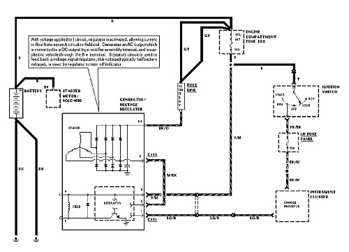
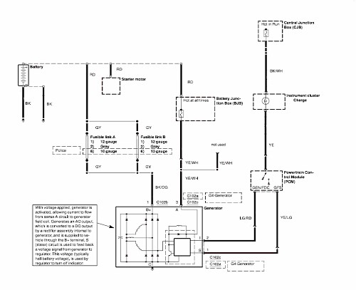
This is the wiring diagram of the charging system used in the 1992-1997 crownvics. All of these cars have a 3G series alternator.
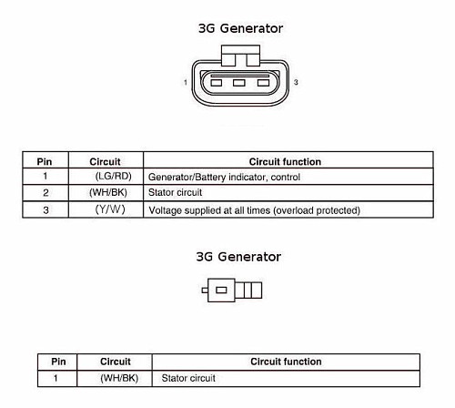
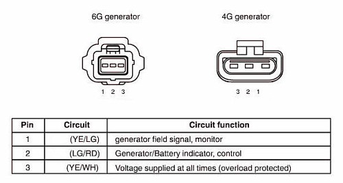
Here are the two regulator related wiring connectors for the 1992-1997 cars. The stator circuit is bridged externally to the regulator on the 92-97 cars rather than internally.
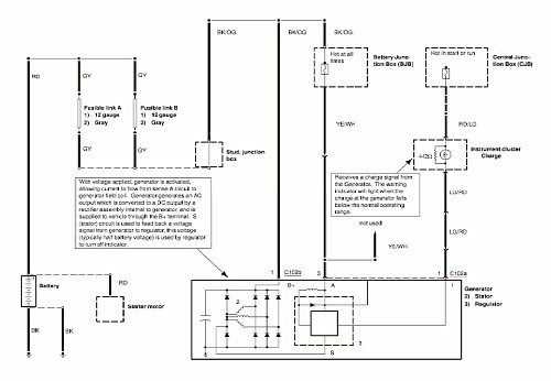
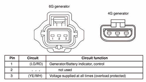
Here is a wiring diagram of the charging system used in the 1998-2002 crownvics. These cars can have either a 4G or a 6G series alternator installed. The control circuitry is the same for both alternators, but the electrical connector that connects to the regulator is different between the 4G and 6G alternators.
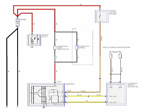
Here is the wiring diagram of the charging system in 2003-2004 crownvics. Starting in the 2003 model year, the alternator became controlled by the powertrain control module instead of using a conventional voltage sense setup like in previous model years.
Also, in the 2004 model year, crown victoria police interceptors recieved a high output 190amp mitsubishi alternator. The high output alternator uses the same electrical connectors as the ford 6G series alternators, but the connectors are in a little different location so you might need to extend the wiring harnesses a little to retrofit a mitsubishi alternator into a car that originally had a ford 6G unit installed.
The 2005-2010 crown victoria charging system is essentially the same as the 2003-2004 crownvic charging system, but a couple of the regulator wires are color coded differently.
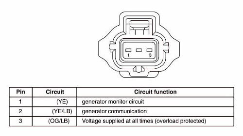
Also, starting in the 2005 model year, the 4G alternator was discontinued in civilian crownvics and replaced by a 6G alternator. So only one regulator connector is used in these cars since the police mitsubishi alternator uses the same electrical connector as the civilian 6G alternator.
- In the 1992-2002 crownvics, you need to connect the charge indicator bulb circuit on the instrument cluster to the alternator regulator in order to have the alternator charge. If you connect a high impedance voltmeter to charge indicator regulator pin, you will see the voltage at ~14 Volts with the ignition key in the run position. And see the voltage drop to ~0 Volts with the ignition key in the off position. You will find a few hundred ohm resistor in parallel with the light bulb in many crownvics so that if the charge warning light on the dashboard fails, the alternator will still charge.
- Fusible Link Colors: Gray=12AWG. Orange=10AWG. Black=8AWG.
- It's really rare to see a charge indicator light fail on the dashboard. But if it does happen and you don't have a resistor in parallel with the charge indicator light, you can end up with an alternator that won't charge. This can be really frustrating for the vehicle owner. In such a situation, the vehicle's owner will have their car towed to a repair shop, the repair shop will note that the alternator isn't charging after charging the battery with an external charger enough to start the car and then connecting a voltmeter to the battery terminals while the car is running. The repair shop will replace your alternator only to find the new alternator still doesn't charge. So the repair shop will likely figure that they just got a "bad" alternator and have the parts store send over another alternator to install. But after installing the second alternator, the repair shop will find the charging system still doesn't work right. Maybe the repair shop will request another alternator from the parts store at this point, or maybe they'll suspect that something is wrong with the vehicle's electrical harness and start troubleshooting your car's electrical harness. Either way, you can end up with your car off the road for a while and incur significant labor costs over a two dollar light bulb.
- There is an "HS-CAN" notation in one of the wiring diagrams that refers to the High Speed Controller Area Network. This is because on the 2006-2010 crown victorias, the powertrain control module signals the instrument cluster charge indicator via high level encoded can bus messages instead of controlling the charge indicator on the instrument cluster with a discrete low level dc signal like on the 2003-2005 cars.
- Ford vehicles use a few different communications systems in between the alternator and the pcm. But all 2003-2010 crownvic alternators use the same signalling setup in between the alternator and the pcm. This is really convienent if you own a civilian 2003-2010 crownvic and want to upgrade to the high output mitsubishi police interceptor alternator.
- Engine idle speed is very important to alternator charging ability at idle. Here is a special service message from ford with some information on the 2003-2004 police interceptor idle strategy:17611 2003-2004 CROWN VICTORIA POLICE INTERCEPTOR - LOW CHARGING SYSTEM VOLTAGE AFTER EXTENDED IDLE
SOME 2003-2004 CROWN VICTORIA POLICE INTERCEPTOR VEHICLES MAY EXHIBIT LOW CHARGING SYSTEM VOLTAGE AND/OR A DEAD BATTERY AFTER PROLONGED IDLE WITH ACCESSORIES ON. TO SERVICE, REPROGRAM THE POWERTRAIN CONTROL MODULE (PCM) TO THE LATEST CALIBRATION LEVEL USING WDS RELEASE B29.9 OR HIGHER. THE NEW CALIBRATION RAISES THE BASE DRIVE IDLE FROM 544 TO 600 RPM, NEUTRAL IDLE REMAINS AT 800 RPM. THE NEW CALIBRATION ALSO DETECTS WHEN THE BATTERY VOLTAGE DROPS BELOW 11.8 VOLTS DURING AN EXTENDED IDLE AND WILL RAMP THE IDLE SPEED UP TO MAINTAIN BATTERY CHARGE. IN NEUTRAL THE IDLE SPEED WILL SLOWLY RAMP UP TO 1100 RPM. IN DRIVE THE IDLE SPEED WILL SLOWLY RAMP UP TO 800 RPM. THE IDLE SPEED WILL RETURN TO THE BASE VALUES (600 IN DRIVE, 800 IN NEUTRAL) WHEN THE BATTERY VOLTAGE RETURNS TO 12.5 VOLTS OR HIGHER.
EFFECTIVE DATE: 03/09/2004
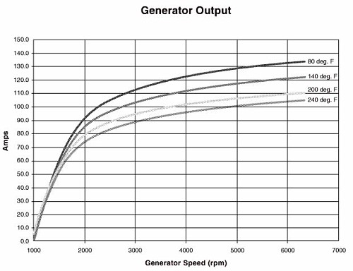
Here is a graph from the 2003 police interceptor modifers guide showing a graph of the 6G alternator shaft speed versus alternator output. Keep in mind that the alternator is overdriven and spins faster than the engine crankshaft.
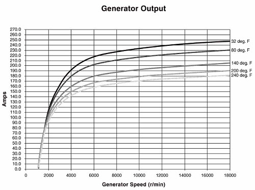
Here is a graph from the 2004 police interceptor modifers guide showing a graph of the 190amp mitsubishi alternator shaft speed versus alternator output. Keep in mind that the alternator is overdriven and spins faster than the engine crankshaft.
Source: https://www.idmsvcs.com/2vmod/alternator/wiring/diagrams/index.html
Posted by: christopherunry199590.blogspot.com
